
SiC Wafer Boat Factory Essentials for High-Purity Semiconductor Processing
2026-09-24
When yields drop and contamination spikes, the culprit often hides in plain sight: the wafer boat. For high-purity semiconductor processing, silicon carbide (SiC) wafer boats have become the backbone of thermal and etch steps—but not all boats are made equal. Semicorex has spent years engineering SiC wafer boats that survive aggressive chemistries and extreme temperatures without shedding particles. In this post, we break down the factory essentials that separate a precision carrier from a liability.
How SiC Boats Withstand Aggressive Cleaning Chemistries
Silicon carbide earns its keep in wafer handling because the same covalent bond that makes it hard also makes it reluctant to react with most acids, alkalis, and oxidizing baths. When a SiC boat drops into a heated sulfuric acid–hydrogen peroxide mixture or a buffered HF solution, the surface forms a thin, passivating silicon oxycarbide layer almost immediately. That layer blocks further attack, so the boat retains its slot geometry and does not shed particles into the bath.
The real test is cycling between aggressive chemistries and rinse/dry steps. Lower-purity ceramic carriers often fail through grain-boundary attack or thermal shock, but high-density SiC keeps grain boundaries tight and handles rapid temperature swings without cracking. Its low porosity means cleaning fluids do not linger in microvoids, which could otherwise cause cross-contamination in later process steps.
That combination of passivation, thermal stability, and low porosity lets a single SiC boat run hundreds of cleaning and oxidation cycles with minimal weight loss and no measurable metallic contamination. The geometry stays stable enough that wafers load and unload without binding, even after months of exposure to aggressive chemistries that would quickly degrade quartz or polysilicon carriers.
The Role of Surface Roughness in Particle Control
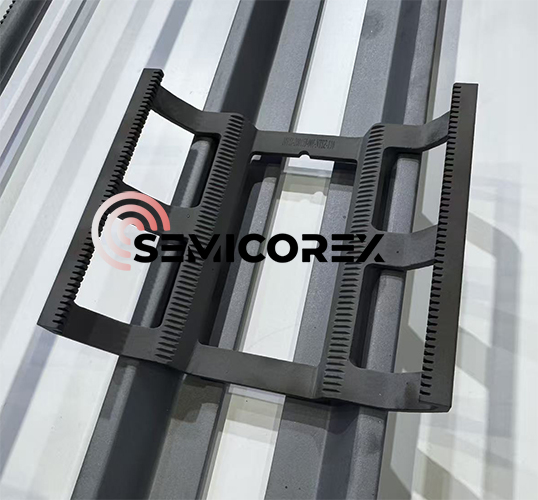
Surface roughness acts as a quiet negotiator between a material and the particles that drift across it. When peaks and valleys are carved at the micron scale, they don't just change how a surface feels—they alter the local airflow, the contact area, and the adhesive forces that decide whether a particle sticks or slides away. In cleanrooms and precision manufacturing, this texture becomes a deliberate tool: too smooth and particles cling by van der Waals forces alone; too rough and they lodge in crevices, stubbornly resisting removal. The trick lies in finding that narrow band where roughness discourages attachment without becoming a trap.
Yet roughness is never a single number. A surface described as Ra 0.4 μm can hide wildly different topographies—sharp peaks shed some particles but anchor others, while rounded undulations may reduce initial adhesion but encourage rolling movement. Engineers often focus on the average deviation, but particle behavior responds more to the skewness, the spacing between features, and the direction of the lay. A polished mold insert and a sandblasted tool face might share a roughness grade yet perform opposite roles in particle retention, which is why mapping the full texture is as important as measuring it.
Perhaps the most overlooked aspect is how roughness changes over time. Contact with abrasives, chemical baths, or even repeated particle impacts erodes the original profile, shifting the balance between capture and release. A surface that once shed powder effortlessly can gradually become a sticky collector, not because its average roughness changed much, but because the sharp edges wore down into smooth flats that maximize contact area. In practice, this means surface roughness is less a fixed property and more a living parameter—one that needs periodic re-qualification if particle control is to stay predictable.
Machining SiC: Balancing Speed and Edge Integrity
Silicon carbide is notoriously unforgiving. Push the feed rate too high and the cutting edge chips within seconds; back off too far and the process becomes economically pointless. The real skill lies in finding that narrow window where material removal stays aggressive enough to matter, yet gentle enough to preserve the tool. Experienced machinists often describe it as listening to the cut—the pitch changes just before an edge fails, and learning to trust that signal beats any fixed parameter sheet.
Edge preparation makes a surprising difference here. A sharp, honed edge cuts cleaner but dies faster under interrupted loads. A slightly dulled or chamfered edge survives longer but generates more heat and micro-cracking risk. The strongest shops don't standardize one geometry; they match edge prep to the specific SiC grade and the feature being machined. Thin walls or sharp internal corners demand a different compromise than flat face milling, and pretending otherwise leads to scrap bins full of shattered inserts.
Coolant strategy is another lever most people ignore. Flood coolant washes away abrasive swarf but thermal shock can fracture the workpiece if the jet is misaimed. Dry machining with high-pressure air avoids that shock but demands faster speeds to keep heat localized in the chip. Some of the best results come from minimal quantity lubrication with a very fine mist, just enough to reduce friction at the shear zone without drenching the part. Getting this balance right is rarely a matter of reading a manual—it comes from running dozens of test cuts and noting exactly where the edge breaks down under each condition.
Cleanroom Logistics for Contamination-Free Boat Assembly
Keeping a boat assembly environment free of contaminants starts long before the first hull panel is lifted. Every cart, rack, and trolley entering the cleanroom follows a one-way flow mapped to the build sequence, so materials never double back through areas where adhesives are curing or sealants are being applied. Floor markings and color-coded zones are refreshed after each shift based on actual foot traffic patterns, not just a static layout, which cuts down on cross-zone particle transfer without requiring extra staffing.
Tool and consumable staging happens in dedicated airlock pass-throughs equipped with tacky mats and HEPA-filtered air showers. Workers wheel in pre-kitted bins of fasteners, fittings, and pre-cut composite cloth, then transfer items onto cleanroom-only carts at the boundary. This handoff point acts as a physical break: anything that touched the outside environment stays outside, while interior logistics rely on low-shedding containers and sealed edge protection. A simple barcode scan at the pass-through logs what came in and when, but the real value is the visual cue that forces a pause before crossing the threshold.
Daily cleanup isn't shoved to the end of a shift. Between major assembly steps, a logistics runner sweeps the main aisle with an anti-static microfiber system and swaps out sticky floor mats at high-traffic junctions. Waste bags are double-lined and removed through a separate exit so dirty air doesn't recirculate near open bonding surfaces. Over time, the team learns which routes generate the least dust by tracking particle counts at fixed monitors, then adjusts cart paths and staging locations accordingly. That kind of feedback loop keeps contamination control practical instead of turning it into a paperwork exercise.
Why Thermal Uniformity Depends on Boat Geometry
The temperature field inside a furnace is never truly uniform, and the boat itself is one of the strongest local modifiers of that field. Every slot, rib, and sidewall changes how radiation reaches the wafers or substrates. A deep slot acts as a partial radiation shield, delaying direct exposure to the heating elements, while a shallow slot lets more energy strike the edge of the part before the center catches up. At the same time, the gaps between the boat and the process tube create narrow channels that either promote or choke gas flow. When those channels are too tight, convection becomes uneven and cold spots persist near the boat surface. In short, the geometry determines not just where the parts sit, but how they exchange heat with their surroundings.
Wall thickness and slot spacing play a more subtle role than most process engineers expect. Thick sections store heat and release it slowly, which can smooth out short-term temperature fluctuations but also produce a thermal lag during ramp steps. If the end plates are thicker than the central dividers, the outer wafers often see a delayed response and a different final temperature. Likewise, uneven slot pitch creates local differences in thermal mass per unit volume. A tightly packed region resists temperature change more than a sparsely loaded section, so the boat itself becomes a source of gradient. This is why two boats with identical outer dimensions can perform very differently if their internal ribs, holes, or support points are not matched to the heater profile.
Practical adjustments to boat geometry usually aim to balance edge losses against center heating. Adding a small opening near the bottom of each slot can increase gas circulation without weakening the structure too much. Slightly rounding the support edges reduces shadowing, allowing more radiant energy to reach the lower surface of each wafer. A variable slot pitch, with tighter spacing near the ends, can compensate for higher heat loss at the furnace mouth and back wall. These changes are not universal fixes, though. A geometry that improves uniformity in one tube may create a reverse gradient in another, especially if the heating element length, insulation thickness, or gas flow direction differs. The only reliable approach is to treat boat geometry as a tunable part of the thermal system, not as a passive holder.
Quality Gates Every High-Purity Boat Must Pass
A high-purity boat doesn't earn its certification by looking clean under a bench light. The first real gate is a bulk trace-metal assay, usually GDMS or ICP-MS, targeting iron, copper, nickel, and alkali metals. If any value creeps past the low-ppb ceiling, the entire lot is quarantined before it can touch a diffusion tube.
Next, surface integrity gets examined at a level that would embarrass a polished lens. White-light interferometry maps roughness across load-bearing slots and contact edges. Any pit, scratch, or residual machining mark deep enough to harbor moisture or process residue means immediate rejection, no rework allowed.
The final gate is a controlled thermal shock cycle. Boats are ramped from ambient to furnace temperature and back, then inspected under polarized light for micro-cracks. Only after passing every gate—trace-metal, surface, and thermal—does a boat receive its serial number and a clean-room packaging seal.
FAQ
SiC offers higher thermal conductivity, better resistance to thermal shock, and lower contamination risk at elevated temperatures compared to quartz, which helps maintain wafer purity during long diffusion or annealing cycles.
Production rooms typically use HEPA/ULPA filtration, workers wear full cleanroom suits, and each boat undergoes ultrasonic cleaning plus vacuum baking before final packaging. Some lines also add a CVD SiC coating to seal surface pores.
If slot spacing or width drifts during firing, wafers can tilt, touch the sidewalls, or create uneven gas flow. Factories often compensate for sintering shrinkage by using pre-sintered SiC or machining green bodies oversize.
The coating acts as a barrier that stops metallic impurities from graphite outgassing, and it provides a dense, non-reactive surface that withstands chlorine or hydrogen atmospheres without flaking.
Steps such as LPCVD polysilicon deposition, silicon carbide epitaxy, and high-temperature oxidation or annealing frequently use SiC boats because metal carriers would warp or introduce contamination at those temperatures.
Operators need to use dedicated quartz or SiC paddles, avoid point impact on slot edges, and preheat the boat gradually before inserting it into a hot furnace. Sudden thermal shock is the main cause of hairline fractures.
Factories often use glow discharge mass spectrometry (GDMS) for trace metal analysis, SEM for surface porosity, and a high-temperature bake-out test to confirm no volatile outgassing occurs.
Different furnace tubes and wafer sizes, such as 150 mm versus 200 mm, require specific pitch, slot depth, and end-plate geometry. Custom designs also help match gas flow profiles to reduce film thickness variation across a batch.
Conclusion
Producing wafer carriers for high-purity SiC processing starts well before the first wafer is loaded. The boats must shrug off aggressive cleaning chemistries—often hot sulfuric acid, hydrogen peroxide, SC1/SC2 blends—without surface degradation or metallic contamination. That chemical inertness keeps the carrier from becoming a particle source after repeated reclaim cycles. Surface finish matters just as much; a controlled, low-roughness interior limits the adhesion of submicron particles while still allowing efficient wetting and drying. On the machining side, shops chase throughput but cannot tolerate edge chipping or micro-cracks along slots, because those defects shed debris during thermal ramps. Cleanroom assembly then takes over: boats are built, inspected, and double-bagged in ISO Class 5 or better environments, with contact points covered and batch records tied to each serial number.
Thermal uniformity inside a furnace or epi reactor is largely a geometry problem. Slot pitch, wall thickness, and the boat's overall thermal mass decide how quickly the carrier reaches setpoint and whether edge and center wafers see the same temperature. A symmetric layout with minimal unnecessary mass reduces lag and prevents localized cold spots that can shift doping or stress the wafer. Before any boat ships, it must pass a sequence of quality gates. These include CMM dimensional checks, white-light interferometry for surface roughness, particle count testing after ultrasonic cleaning, chemical exposure coupons, and repeated thermal cycling to screen for latent cracks. Only carriers that clear every gate are released for high-purity semiconductor processing.
Contact Us
Contact Person: Svenja Wei
Email: [email protected]
Tel/WhatsApp: +8613567891907
Website: https://www.semicorex.com