


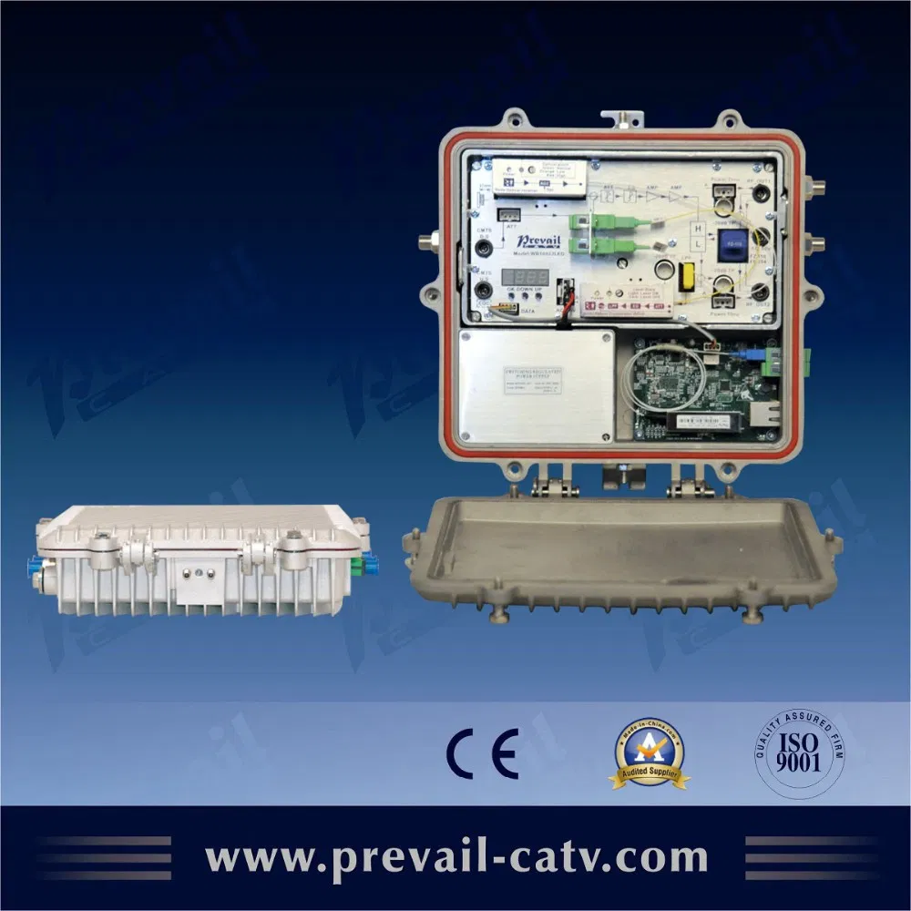

Hfc Fiber Optical Receiver FTTH Node
1. Product SummaryWR1002JLED is a new modular two-output CATV network optical receiver. It adopts modular design, use more flexible. Microprocessor control, digital display the parameters, the engineering debug is especially easy. It is the main equipment to build the CATV network. 2. Performance Ch......
Send Inquiry
Product Description
1. Product Summary
WR1002JLED is a new modular two-output CATV network optical receiver. It adopts modular design, use more flexible. Microprocessor control, digital display the parameters, the engineering debug is especially easy. It is the main equipment to build the CATV network.
2. Performance Characteristics
High response PIN photoelectric conversion tube.
Optimized circuit design, SMT process production, optimized signal path, make the photoelectric signal transmission more smooth.
Specialized RF attenuation chip, with good RF attenuation and equilibrium linear, high accuracy.
GaAs amplifier device, power doubler output, with high gain and low distortion.
Single Chip Microcomputer (SCM) control equipment working, LCD displaythe parameters, convenience and intuitive operation, and stable performance.
Excellent AGC performance, when the input optical power range is -9~+2dBm, the output level keep unchanged, CTB and CSO basically unchanged.
Reserved data communication interface, can connect with the Ethernet transponder, access to network management system.
Return emission can select burst mode to sharply decrease the noise convergence and reduce the forepart receiver number.
ONU module optional.
3. Technique Parameter
3.1 Link testing conditions
The technique parameters of this manual according to the measuring method of GY/T 194-2003 <Specifications and methods of measurement on optical node used in CATV systems>, and tested in the following conditions.
Testing conditions:
- 1. Forward optical receive part: with 10km standard optical fiber, passive optical attenuator and standard optical transmitter composed the testing link. Set 59 PAL-D analog TV channel signal at range of 45/87MHz~550MHz under the specified link loss. Transmit digital modulated signal at the range of 550MHz~862/1003MHz, the digital modulated signal level (in 8 MHz bandwidth) is 10dB lower than analog signal carrier level. When the input optical power of optical receiver is -1dBm, the RF output level is 108dBμV, with 8dBoutput tilt, measure the C/CTB, C/CSO and C/N.
- 2. Backward optical transmit part: Link flatness and NPR dynamic range are the link indexes which is composed of backward optical transmitter and backward optical receiver.
Note: When the rated output level is the system full configuration and the receiving optical power is -1dBm, equipment meets the maximum output level of link index. When the system configuration reduce (that is, actual transmission channels reduce), the output level of equipment will be increased.
Friendly Notice: Suggest you setting the RF signal to 6~9dB tilt output in the practical engineering application to improve the nonlinear index (behind the node) of the cable system.
3.2 Technique Parameters
Item | Unit | Technical Parameters | |||
Optical Parameters | |||||
Receiving Optical Power | dBm | -9 ~ +2 | |||
Optical Return Loss | dB | >45 | |||
Optical Receiving Wavelength | nm | 1100 ~ 1600 | |||
Optical Connector Type |
| FC/APC, SC/APC or specified by the user | |||
Fiber Type |
| Single Mode | |||
Link Performance | |||||
C/N | dB | ≥ 51 (-1dBm input) | |||
C/CTB | dB | ≥ 65 | Output Level 108dBμV EQ8dB | ||
C/CSO | dB | ≥ 60 | |||
RF Parameters | |||||
Frequency Range | MHz | 45 ~862/1003 | |||
Flatness in Band | dB | ±0.75 | |||
Rated Output Level | dBμV | ≥ 108 | |||
Max Output Level | dBμV | ≥ 114 | |||
Output Return Loss | dB | (45 ~550MHz)≥16/(550~1003MHz)≥14 | |||
Output Impedance | Ω | 75 | 75 | ||
Electronic Control EQ Range | dB | 0~15 | 0~15 | ||
Electronic Control ATT Range | dBμV | 0~15 | 0~15 | ||
Return Optical Emission Part | |||||
Optical Parameters | |||||
Optical Transmit Wavelength | nm | 1310±10, 1550±10 or specified by the user | |||
Output Optical Power | mW | 0.5, 1, 2 | |||
Optical Connector Type |
| FC/APC, SC/APC or specified by the user | |||
RF Parameters | |||||
Frequency Range | MHz | 5 ~ 65 (or specified by the user) | |||
Flatness in Band | dB | ±1 | |||
Input Level | dBμV | 72 ~ 85 | |||
Output Impedance | Ω | 75 | |||
NPR Dynamic Range | dB | ≥15 (NPR≥30 dB) Use DFB laser | ≥10(NPR≥30 dB) Use FP laser | ||
General Performance | |||||
Supply Voltage | V | A: AC (150~265)V; B: AC (35~90)V | |||
Operating Temperature |
| -40~60 | |||
Storage Temperature |
| -40~65 | |||
Relative Humidity | % | Max 95% no condensation | |||
Consumption | VA | ≤ 30 | |||
Dimension | mm | 280(L)*260(W)*70(H) | |||
Note: The forward RF parameters are tested under the condition of using GaAs 25dB power doubler module in the last stage. Use other module, the parameters will be slightly different.
Burst Mode (Select this mode, see below) | ||
Optical Output Power (Close the burst mode) | dBm | -30 |
Laser Turn On Threshold | dBμV | ≥70 |
Laser Turn Off Threshold | dBμV | ≤62 |
Laser Turn On Time (t1) | us | 0.5≤ t1 ≤1 |
Laser Turn Off Time (t2) | us | 0.5≤ t2 ≤1.5 |

 -Pon Wdm Optical Mini Node 1270/1577nm")


 -Pon")
 -Pon Wdm 1270/1577nm")